An EBay acquisition from an non-ham who had acquired it from a "Silent Key". It was claimed to be fully working.
However, as it turned out this radio had all the "classic FT102" problems with relays, and thus I was introduced to the mad mad world of restoration.
After doing some research, particularly on the "Fox Tango" web site (see the links page) I was able to obtain replacement relays (plus a CW filter for good measure) and spent a happy couple of days disembowelling the rig to replace the recalcitrant relays on the RF board.
This process will be documented here in due course.
On May 8th 2008 I replaced the clarifier relay on the local board, a relatively simple job, though it was quite an effort to raise the board through 90 degrees to allow access to the print due to the congestion of wires. As I intend to fit an X-lock by Cumbria Designs to this radio, I took the opportunity to connect a flying wire to the relevant part of the circuit (again, I hope to document this in due course), and to change the value of resistors R163 through R166 to 10kohms in preparation. The clarifier circuit is now performing perfectly. The FT-102 isn't a particularly bad radio for drift, but it is physically quite massive, consequently it can take many hours of operation to achieve thermal equilibrium, therefore it seemed to be an ideal candidate for trying out 21st-Century VFO stabilisation techniques!
Update November 2022 (!) Clearly time has moved on, and, sadly Cumbria Designs are no more. There will never be an X-Lock fitted to this transceiver. Note that the above link goes to an archived copy of their former web site.
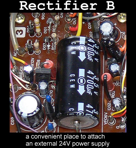
One favourite technique of mine when I am working on or repairing hybrid equipment is to power the low power stages (i.e. not those requiring high voltages) from a current limited external power supply. There is usually a good place in the circuit to attach such a supply, often across the main low voltage reservoir capacitor. In the case of the FT-102 the capacitor in question is on the Rectifier B board, and conveniently this is an axial-lead capacitor, so clipping some temporary leads onto it is an easy task. Just be careful to get the polarity correct! I did this after the clarifier relay replacement, and found that the FT-102 requires a 24V supply and takes some 1200mA just to run the stages powered up during receive. No wonder this radio runs quite warm!
I have used this rig on BPSK31, and the transmitter linearity is excellent. The "headroom" which the substantial PA gives you with the three 6146s in parallel also make this an excellent rig for Digital SSTV. (DRM)
The main outstanding faults/annoyances with this rig are the extremely noisy AF Gain pot (especially in the quadrant which is the most used!) and there is an imbalance in the SSB frequency response between USB and LSB, presumably due to the carrier insertion points needing to be trimmed. Fortunately this is not normally a difficult job to do on this type of rig. Noisy pots appear to be another common ailment.
I also have a brand new (NOS) second IF CW filter to fit on the IF board when I get round to it ...
As with all restoration projects of this kind, one has to justify in one's own mind the value in terms of both financial cost and effort of one's labours. My view is that it is most certainly worthwhile for a number of reasons. The first is that, in the case of the FT-102 the performance of the radio when it is working close to its peak performance is very good, and it can hold its own with many if not most of its more modern descendants. The second, interestingly is that it makes one appreciate just how far the technology has progressed since the FT-102 was a top-of-the range current model. It certainly helps one keep a sense of proportion!
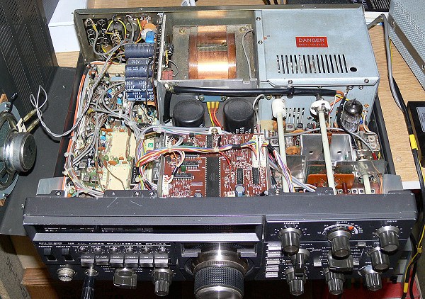
The picture below was taken the first time I took the cover off the rig.