 elay which switches the attenuator in and out of circuit. To be resolved!
Another EBay acquisition, this rig was bought with "all options loaded", meaning internal PSU, narrow CW filter, and factory-fitted memory board. I have since acquired a 6kHz bandwidth IF filter suitable for the Yaesu rigs of this period. This has been fitted and works splendidly. Actually the only other suitable radio is the FT-902DM which has a "proper" provision for an AM filter. The use of such filters in the FT-101Z series has been tried but, frankly is a bit of a bodge! More of this elsewhere, eventually ...
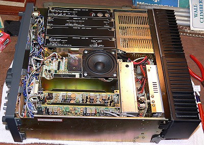
This is a really nice example, in excellent cosmetic condition apart from some corrosion on the upper part of the case which looks like the residue of a chemical spill or similar. The front panel is almost perfect.
Conceptually, this feels like a solid-state version of the FT-902 series, between the late hybrid models and the FT-ONE, which was all solid-state but with a wide band receiver. However this radio doesn't feature the curious PLL circuitry used in the FT-902, nor does it have a built-in CW keyer, so I suppose in that respect it is probably more akin to the FT-101ZD series! Band selection uses relays rather than relying on a multi-section wafer switch.
There are some minor operational issues, the RF attenuator on the receiver is either 0dB or "infinite" dB - this is apparently a very well known issue with the relay which switches the attenuator in and out of circuit. To be resolved!
Additionally the memory functions don't appear to be working, although the vendor claimed it was OK. This rig has a reputation for problematic memory functions - I have yet to investigate though I have recently acquired a spare memory module. Potentially the memory functions could be very useful for "high stability digital mode operation" as the VFO stability of this rig leaves something to be desired.
Apart from these niggles, this rig has a real "quality feel" about it and deserves to be brought up to scratch.
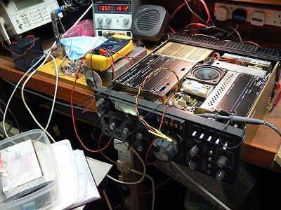
Just recently, this rig started intermittently exhibiting a curious fault.
The rig would show symptoms of something akin to "VSWR foldback" - the power output would drop to a maximum of around 15W the forward power metering would show zero forward power and there would be significant reflected power.
This had nothing to do with the antenna load, as the fault symptoms were the same into my dummy load, with a different patch cable.
Fortunately the fault was present more than it was absent, so I stood a chance of being able to find it!
I reasoned that it may well be something to do with the directional coupler board which is located snugly (very snugly!) at the RF input/ouput jack.
Thus the rig was dismantled in order to extract the coupler board, and one or two very suspect looking joints were spotted and resoldered.
The rig worked fine when tested, but unfortunately started misbehaving again in an identical fashion just as soon as I reassembled it and put the covers back on!
Undaunted, I took the rig apart again, an fortunately discovered that the fault had become "microphonic" in that it responded to judicious tapping around one of the main wiring looms.
I eventually spotted a connector which appeared to be not correctly seated, this was corrected and the fault was cleared.
Which connector was it? To my great surprise the connector in question is the one which connects the front panel Noise Blanker control to the IF board! I am still somewhat puzzled by this, but I backtracked and deliberately misaligned the plug deliberately and the fault returned, so I wasn't imagining it!
 One of the issues with radios of this vintage is that of slow steady VFO drift. One of my long term of objectives is to tackle this problem using modern techniques to establish whether or not performance can be improved.
After quite a long period of deliberation, I decided that of all the "classic" radios in my collection, this radio in particular was worthy enough to receive a special treat - that of an X-lock module, designed and supplied by now sadly defunct Cumbria Designs
The ultimate objective would appear to be to achieve a level of frequency stability whereby one can leave the radio to take part in the WSPR operations where long unattended operating periods are the order of the day.
I had bought an X-Lock kit some time ago thinking originally of building it into my FT-102, but, partly because someone had done that before, but mainly because I enjoy using the FT-107 so much that I decided eventually to go down that particular route.
 The X-Lock is a very straightforward kit to complete and shouldn't give anyone with a moderate amount of kit-building experience any difficulties. All components are through-hole (ie not Surface Mount), and there is just the one AOT (adjust on test) component which may require some experimentation.
The trickiest part is figuring out the interfacing between the rig and the X-lock. You, as the builder have to decide whether to use the existing RIT circuitry to accomplish the required nudging of the frequency, or to use the supplied varactor (actually an LED used as a varactor).
I decided I would use the existing circuitry, as this method had been used before by an FT-102 owner the details of which had been published on the then Cumbria Designs web site.
After some studying of the FT-107M circuitry I came up with a scheme which worked a treat. The supplied AOT resistor which controls the loop time constant was found to be not quite right for my implementation but it only took a couple of tries to end up with a satisfactory value.
The results though have been outstanding to say the least, and the frequency stability of the transceiver is now comparable to that of a modern, fully synthesised unit, and easily capable of being used for modern digital modes, which was the original objective.
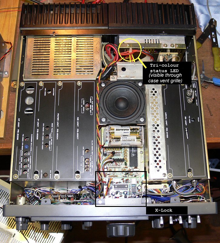
There is even a neat place within the FT-107M to mount the X-lock, almost as though it had been designed with that in mind!
Hopefully the following photographs will explain all ... (Click on any image for a full size view)
 | View of X-Lock installation in FT-107 (top) |
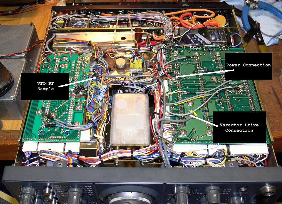 | View from underneath |
 | Interfacing Schematic |
| IW3ICH 10MHz Beacon WITHOUT X-Lock | |
| IW3ICH 10MHz Beacon WITH X-Lock | |